Table of Contents
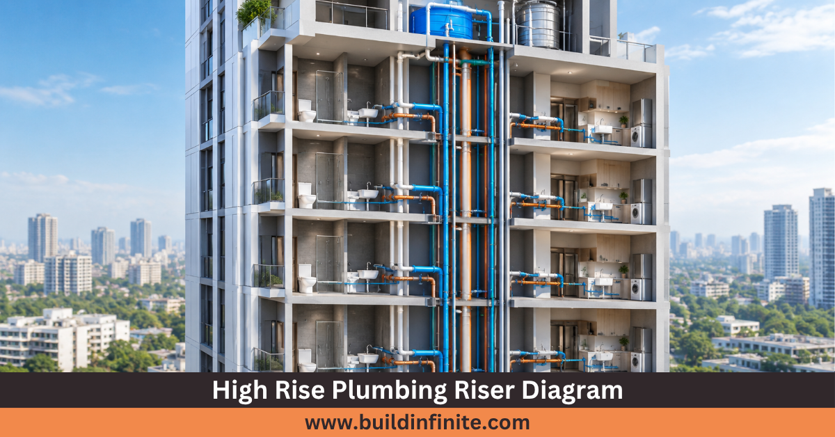
ToggleEvery tall tower relies on an extensive plumbing network running out of sight behind drywall, drop ceilings, and service shafts. The High Rise Plumbing Riser Diagram brings this entire setup into focus. It gives you a clean, vertical look at every pipe run, fixture, branch line, shutoff valve, and connection across every floor. Skip the riser drawing, and sorting out your pipe routes turns into a massive headache fast.
A standard plumbing layout diagram only shows you things floor by floor, but a riser diagram tracks how water and waste travel up and down the structure. That vertical view gives architects, project engineers, site contractors, and BIM modelers a crystal-clear look at the entire plumbing system design.
A sharp diagram makes aligning plumbing with structural framing, duct runs, and electrical trays far simpler. Even better, it catches route clashes long before crews show up on site. This guide walks you through practical plumbing riser design, sheet requirements, trade coordination, and everyday BIM workflows.
What Is a High Rise Plumbing Riser Diagram?
A High Rise Plumbing Riser Diagram shows vertical pipe runs in a tall building. It connects various floor levels and shows utilities runs in service chases and shafts.
A conventional diagram shows plans in a single elevation. The riser diagram shows the vertical ties between stories. It connects vertical circulations such as water, waste and vent pipes. It also connects vertical ties to other building service equipment such as air handlers and mechanical equipment.
Pipes shown in a riser diagram may include overhead pipes and equipment ties, and building services ties such as fire protection, medical gases and other building services equipment. The diagram also identifies floor levels and major connection points. Consequently, engineers can understand how individual floors connect with the main plumbing network.
A plumbing system riser diagram normally separates different services for better readability. For instance, a domestic water riser diagram can illustrate cold and hot water distribution. Meanwhile, a sanitary riser diagram can show soil, waste, and vent connections.
The drawing should remain clear even when the building contains dozens of floors. Therefore, linework, symbols, tags, pipe sizes, levels, and notes require careful organisation.
Key Elements of High Rise Plumbing Riser Design
Getting your plumbing riser design right takes solid base files. Slab-to-slab dimensions, bathroom and kitchen positions, mechanical shafts, and basement pump rooms directly shape the layout on paper.
A clean water supply riser diagram tracks where the city main comes in and how that water moves upward. It details roof storage tanks, booster sets, pressure zones, regulating valves, and the branch lines branching into each story.
Waste lines demand just as much care. An accurate drainage riser diagram needs to clearly show main vertical waste stacks, pitched horizontal branches, cleanout plugs, vent pipes, and the final tie-in to the municipal sewer main.
Managing pressure gets trickier the higher you build. Upper penthouse levels need extra boost, while lower floors can blow out fixtures without proper control. That is why high rise plumbing design breaks the building down into dedicated pressure zones.
Sizing your lines correctly is vital. Peak water demand, fixture unit counts, friction loss, flow speed, and tight shaft space all dictate the sizes shown on the plumbing piping diagram. Your plumbing riser plan has to line up perfectly with architectural layouts. If it drifts, pipes will cut straight through structural beams, drywall, or shared mechanical corridors.
Plumbing Riser Diagram for Commercial and Residential Buildings
Setting up a plumbing riser diagram for commercial buildings is usually far more complex than drafting a residential plumbing riser diagram. Commercial buildings plumbing drawings must account for office suites, hotel rooms, health clinics, busy retail spaces, and industrial kitchens, each with different water supply, drainage, and sanitary requirements.
Each project has its own set of issues. For hotels, it’s the large volume of domestic water with an even larger drainage volume. Peak morning use in a hotel can test the limits of any plumbing system. Healthcare facilities require specialty plumbing for medical gases and waste.
Residential plumbing systems tend to repeat on each story of an apartment building. Therefore, it is best to represent plumbing horizontally like a residential plumbing riser diagram.
Vertical runs in a plumbing system can be represented with stacked wet walls. Even buildings with repeating levels have quirks. Framing beams change thickness, unit layouts shift, and service corridors move as the building steps back.
A commercial plumbing riser often runs separate lines for podium retail, parking garages, and office towers above. That means your plumbing schematic diagram must cleanly separate each loop and spell out its role.
The same rule holds true for luxury residential towers. A tidy plumbing riser drawing saves installers time, makes city inspections painless, and helps facility managers tackle future repairs without guessing.
Water Supply Riser Diagram and Pressure Management
Moving water up high is a constant fight against gravity. Water generates substantial weight when compressed to a small space. The pressure on the lower levels of a skyscraper from all the water stored in the risers creates a vacuum effect on the upper levels. This means that your water supply riser diagram has to account for pressure and friction loss at each floor.
The higher the building, the more complicated the plumbing system has to be. In addition to break tanks, systems can include zoned hydronic loops and variable speed pumps. The incorporation of these components relies on the result of hydraulic calculations and local building codes.
Pressure zoning can prevent excessive pressure on lower floors. At the same time, upper floors must receive adequate flow and pressure. The plumbing piping diagram should therefore communicate major equipment and control points clearly. Pump tie-ins, overflow levels, valve tags, pipe diameters, and zone breaks should jump off the page at a glance.
Clean drafting keeps jobsite crews moving forward. Accurate plumbing construction drawings remove guesswork when plumbers turn lines on a page into copper, steel, and cast iron.
Sanitary Riser Diagram and Drainage Planning
Soil drainage needs tight vertical coordination since it relies purely on gravity fall. A clear sanitary riser diagram illustrates exactly how bathroom sinks, water closets, and floor drains hook up to vertical soil and waste stacks.
Riser drainage diagrams completely show how relief and vent lines run through a building. Proper venting allows air to mix and thus prevents vacuum conditions that can break trap seal. It also prevents sewer odors from entrancing building interiors.
Maintaining a proper slope is important for branch waste piping, and for the vertical stack, passage through floor and slab openings is important.
A dedicated sewer riser diagram links indoor waste lines to the municipal sewer tie-in out front. Getting this right means checking invert levels against civil site drawings.
Tall floor plates multiply the risk of stack issues. Always review your drainage stacks against column drops, transfer slabs, and architectural walls. A thoughtful plumbing riser plan also spots service access early. Cleanout plugs, shutoff valves, and test tees must sit where building operators can reach them later.
Plumbing Riser Diagram Design and BIM Coordination
Modern plumbing system design is built around BIM tools. Adopting plumbing BIM design lets teams build out piping inside a shared, live digital building model.
With plumbing BIM modeling, pipes, valves, fittings, pumps, and chases exist as fully detailed 3D objects. Catching tight physical clashes in 3D is worlds faster than flipping through flat 2D sheets. Your MEP plumbing design links right into architectural walls, concrete slabs, duct networks, and cable paths. Automated clash checks flag hard hits before anything gets ordered or cut.
Field-ready plumbing coordination drawings give installers everything they need on site. They package floor plans, section cuts, valve schedules, sleeve details, and 3D plumbing isometric riser diagrams together. BIM software makes updates much cleaner. When an engineer resizes a pipe or shifts a shaft, the model updates plans, elevations, and schedules in one go.
Keep in mind that software is just a tool. Clean design still depends on accurate flow calculations, solid modeling standards, tight pipe specs, and experienced engineering judgment.
Common Information Shown in a Plumbing Riser Drawing
A plumbing riser drawing should communicate essential information without becoming visually crowded. Good graphic organisation allows technical teams to read the drawing quickly.
| Drawing Information | Typical Purpose |
|---|---|
|
Floor levels |
Shows vertical building relationships |
|
Pipe sizes |
Supports installation and coordination |
|
Pipe Tags |
Identifies individual services |
|
Valves |
Shows control and isolation points |
|
Fixtures |
Indicates plumbing connections |
|
Equipment |
Identifies pumps, tanks, and related systems |
|
Flow direction |
Clarifies water or drainage movement |
|
Shaft locations |
Defines vertical service routes |
|
Connection points |
Shows links between systems |
|
Notes |
Provides essential technical information |
Clean presentation across your plumbing design drawings is critical. Pipe tags, valve symbols, shorthand codes, line weights, and callouts must stay uniform on every sheet. While a plumbing schematic diagram shows system logic and flow paths, detailed plumbing construction drawings hand crews the exact field measurements they need to install.
Each sheet type does a specific job. Pairing system schematics with dimensional site drawings creates an airtight documentation set.
How to Prepare a High Rise Plumbing Riser Diagram
Once the latest architectural and structural drawings are available, begin design work by locating items such as floor penetrations and partitions, and establishing fixture numbers and pump locations. This information serves as a basis for the design and provides a starting point for the construction of the system.
Locate the risers and establish the main service shaft. Check the service zones against such items as concrete columns and deep transfer beams, and consider the clearance to the finished ceiling.
From there, draft out domestic water, sanitary, drain, and vent stacks. Size every pipe run and valve based on flow demand formulas and regional plumbing codes. Keep coordination running across every design phase. An architect shifting a bathroom or an engineer thickening a floor slab immediately alters your vertical runs.
Finally, run the finished plumbing riser drawing through a thorough quality check. Verify line sizes, invert elevations, equipment tags, and shaft penetrations before sign-off. Following these steps delivers dependable plumbing design drawings that build smoothly on the jobsite without rework.
Common Challenges in High Rise Plumbing Design
High-rise projects introduce several coordination challenges. Limited shaft space is one of the most common issues. Multiple plumbing stacks may need to share a narrow vertical zone.
Controlling pressure is always an uphill battle in tall towers. Supply loops must feed top floors without blowing out fittings on the floors below.
Waste routing gets messy just as fast. Horizontal stack offsets often run into deep transfer beams and shallow ceiling bulkheads. Sharing ceiling space with other trades is a constant fight. Sheet metal ducts, cable trays, sprinkler mains, and plumbing lines all fight for the same few inches.
Late project revisions only add fuel to the fire. Running regular clash detection with plumbing BIM modeling stops costly change orders before they hit the field. Clear drafting is just as important as good calculations. Even a code-compliant layout falls apart on site if annotations are blurry, symbols clash, or dimensions go missing.
Conclusion
A High Rise Plumbing Riser Diagram shows the real-world vertical backbone of a building. It bundles water distribution, sanitary stacks, vent lines, pump assemblies, and floor tie-ins into one easy-to-read drawing.
High-quality plumbing riser design keeps engineers, field supers, trade contractors, and BIM managers on the same page. Catching line conflicts on paper prevents costly delays on the slab. Moving to plumbing BIM design ties riser data right into the broader project model. Still, high-tech tools only work when backed by precise engineering and real trade experience.
If you need support with plumbing BIM modeling, site-ready plumbing construction drawings, or clash-free MEP plumbing design, reach out to our team today. We can review your building files and set up an efficient modeling workflow.
Get a quote today for high-rise plumbing design, plumbing riser drawings, and BIM coordination services.
Frequently Asked Questions
Why is plumbing riser design important for high-rise buildings?
Solid plumbing riser design keeps vertical mains, floor runouts, pressure setups, soil stacks, and shaft sizes fully aligned. It also gives architects, engineers, BIM technicians, and trades a shared roadmap to build from.
What does a domestic water riser diagram show?
A domestic water riser diagram outlines the clean water delivery loop through a building. Depending on setup, it shows storage cisterns, booster pumps, regulating valves, pressure zones, pipe runs, and branch takeoffs for each floor.
Can BIM be used for high-rise plumbing design?
Yes. Using plumbing BIM modeling provides the ability to model precisely the horizontal and vertical runs of piping in a building, including fittings, fixtures, and related equipment. It also provides the ability to generate automated clash resolutions and constructability reviews and plumbing coordination and installation documents.