Table of Contents
ToggleCommercial Electrical Plans provide building safety and preparedness for everyday activities. Planning for every electrical outlet and device is crucial. In addition, commercial work requires more planning and coordination than residential work.
When designing an electrical plan, many other elements must be taken into account, including architecture, structure, plumbing, HVAC, fire protection, and the site in general. A plan that addresses these factors eliminates confusion and helps the contractors understand equipment, circuits, and interconnections.
More recently, three-dimensional CAD drawings are being used for design and are proving very effective for design documentation and plan review.
The process starts with project information and ends with a checked drawing package. Along the way, designers review loads, equipment, circuits, lighting, power distribution, and safety requirements. A strong plan does more than look neat on paper. It gives the construction team a practical electrical roadmap.
What Is a Commercial Electrical Plan?
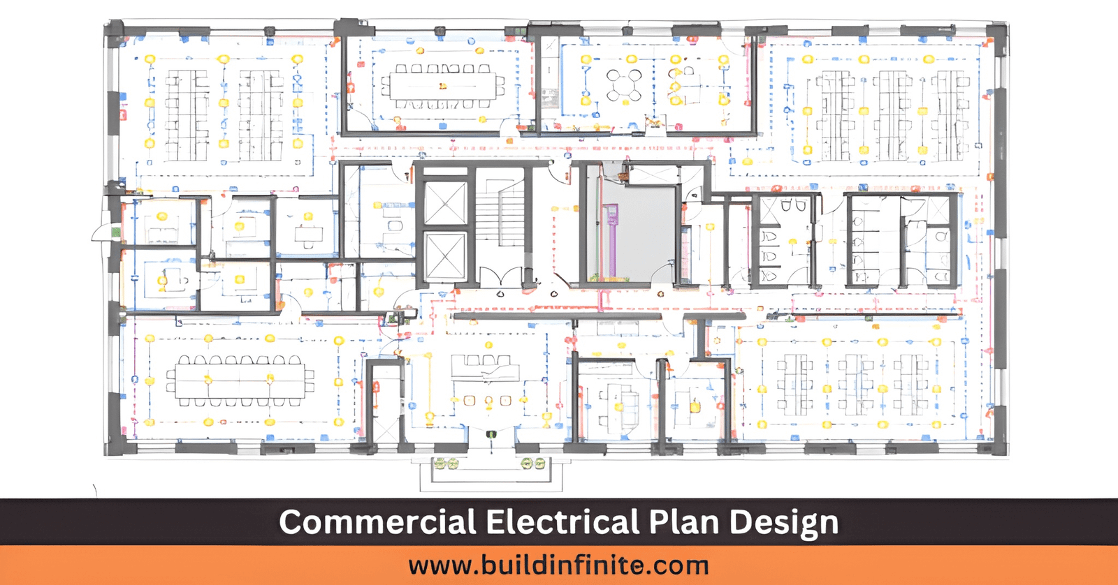
A Commercial Electrical Plan is a drawing that illustrates the various electrical components for a commercial space. This can include, but is not limited to, lighting, receptacles, distribution components, circuits, power connections, and emergency systems.
Although a rough sketch may give an idea of the layout, this type of plan contains information that is key to the plan. This can include electrical symbols and circuit routes, as well as equipment and connection points with pertinent notes.
These plans are usually done to coincide with architectural and engineering plans. The electrical plan for the commercial space can be influenced by a number of things, including function of the space, location of doors and walls, ceilings, and equipment.
Circuit information and equipment requirements may be shown in a plan view or in a detail or schedule. These may also show information related to clearances and requirements for the installation.
Commercial Electrical Plans: Step-by-Step Guide
Step 1: Collect Project Information
The first step is acquiring accurate project information. With less than ideal information, even the best drafting can yield a bad result.
The design team looks at architectural and structural drawings, as well as information about the project equipment, site conditions, and requirements. For renovation projects, we look at the existing electrical information.
Different types of facilities have different types of loads. For example, a warehouse doesn’t need as much electrical load as a healthcare facility. A restaurant would have a different load than a data center.
Existing plans deserve a second look. An as-built plan of the electrical system of the facility may show existing panels, circuits and equipment and their routes of distribution. Out-of-date plans may need to be confirmed through field verification.
Local codes must also be considered. Electrical systems and equipment must also be designed in accordance to the applicable regulations, requirements of the utility, and project standards. For projects using the NEC, the latest edition of the NFPA 70 must be referenced.
For broader technical drawing guidance, Autodesk’s electrical drawing resources provide useful information about electrical drawings, symbols, and CAD workflows.
Step 2: Review the Architectural Floor Plan
The architectural floor plan becomes the foundation for electrical placement. Therefore, the drawing should be reviewed before electrical symbols are added.
Rooms, walls, doors, ceilings, furniture, and equipment affect the placement of electrical devices. For example, a switch needs to be accessible after doors and furniture are installed.
The design team reviews reflected ceiling plans when they are available. Lighting and emergency devices, as well as ceiling sensors and other ceiling-mounted devices, all need proper interdepartmental coordination.
At this stage, an electrical floor plan AutoCAD drawing can establish the basic working environment. Correct layers, scales, symbols, references, and drawing standards should be maintained. A clean base file also reduces later corrections. Small drafting mistakes can become expensive when they reach construction documents.
Step 3: Determine Electrical Loads
Load planning forms a major part of commercial electrical plan design. The system needs enough capacity for current requirements while allowing sensible future growth.
The design team identifies the major pieces of equipment and electrical loads such as HVAC equipment, Kitchen Equipment, Machinery, Lighting, Receptacles, Lifts, Pumps, and specialty systems. Next, the loads are organized by distribution requirements. Panels and feeders can then be planned around the expected demand.
The calculation method depends on the project location and applicable electrical standard. Therefore, assumptions should never replace local engineering requirements. A good load schedule keeps the design organized. It also provides useful information for panel schedules, equipment selection, and distribution planning.
Step 4: Plan Lighting and Power Layouts
Lighting and power systems form the visible part of many commercial electrical drawings. Their locations should support both building use and practical installation.
Lighting layouts and power layouts both illustrate their respective layouts, including emergency lighting, switching and controls, receptacles, connections, outlets, and other elements.
The design should consider accessibility and actual room use. A technically correct outlet can still create problems if it sits behind equipment.
Similarly, lighting should coordinate with ceilings, ducts, sprinklers, beams, and architectural features. Early coordination prevents crowded ceiling layouts later. The electrical plan blueprint should remain easy to read. Clear symbols and logical circuit references help contractors interpret the drawing quickly.
Step 5: Develop Distribution and Circuit Information
Once loads, lighting, and power requirements are established, distribution planning can move forward. Panels need suitable locations, access, and coordination with other building systems. Main distribution equipment also requires appropriate space and connection planning.
Circuit information should remain consistent across drawings. Panel schedules, circuit numbers, equipment tags, and load information should match.
Commercial electrical drawing packages may include single-line diagrams alongside floor plans. These diagrams explain the relationship between incoming power, distribution equipment, panels, feeders, and major loads. For larger properties, electrical engineering blueprints may also include detailed riser diagrams, equipment schedules, grounding information, and other technical documentation.
Step 6: Create the CAD Electrical Layout
CAD drafting transforms design information into construction documentation. An AutoCAD electrical layout plan shows accurate geometry, organized layers, and reusable symbols with clear annotations.
Drafting adheres to standards. Line weights, text sizes, symbols, layers, dimensions, and sheet layouts remain controlled throughout the project. Various CAD formats make collaboration simple. Electrical drawings can be shared with architects, engineers, contractors, and other project participants.
CAD software does not replace engineering judgment. Although CAD can accurately portray a design, the design still requires a qualified review.
Step 7: Coordinate With Other Building Systems
Good coordination is key to transforming a good Commercial Electrical Plan into a good construction document.
Electrical routes need to compete for space against other building systems such as HVAC, plumbing, and architectural and structural features, as well as fire protection systems.
In addition to interdisciplinary coordination, intradisciplinary coordination is required. Conflicts arise during the design and construction process, and the earlier they are identified and resolved, the lower their impact on project costs and schedule.
BIM facilitates the process of intradisciplinary and interdisciplinary coordination. For BIM-based projects, electrical systems can be modeled and coordinated in the same building information model as other building systems.
Digital documentation for commercial projects is becoming increasingly integrated. As such, the electrical drafting and MEP engineering teams, as well as the architectural drafting teams, are often on the same project.
Step 8: Review Codes, Standards, and Safety Requirements
Drawings must be made to meet the requirements applicable to their location. Requirements may vary based on country, state, city, utilities, building types, etc.
Some jurisdictions require the consideration of multiple codes, rules, and standards, including electrical codes, building regulations, fire codes, energy codes, accessibility codes, and utility standards.
NFPA 70, more commonly known as the National Electrical Code, covers the electrical requirements for a wide variety of projects using the National Electrical Code. The 2026 edition of NFPA 70 includes various revisions to requirements such as load calculations, grounding requirements, requirements for PV systems, energy storage systems, electric vehicle charging systems, and more.
However, the applicable local authority remains important. A drawing should never assume that one code applies universally.
Step 9: Perform a Detailed Drawing Review
Each drawing must undergo a thorough review before being included in the drawing package. During the review, each element, including but not limited to references, equipment locations, circuit information, panel schedules, notes, dimensions, symbols, and electrical calculations, should be reviewed.
There should be consistency throughout the drawings. Panel names shown on floor plans should be the same on the panel schedule. Equipment tags should be consistent across related drawings. The review should also find coordination conflicts.
An additional quality control step could be a second-person review. New editors often see small inconsistencies that are overlooked by repeat editors.
Step 10: Prepare the Final Electrical Drawing Package
The final stage is taking the approved documents and putting them in a clear issue set. As per the project requirements, the package may include electrical floor plans, lighting plans, power plans, single-line diagrams, panel schedules, load schedules, details, notes, legends, and equipment information.
Drawing titles and revision information should remain consistent. File naming should also follow the project’s documentation standards.
For construction, the final set should communicate enough information for installation and coordination. For record purposes, updated documentation may later become an electrical as-built plan.
Good documentation remains useful after construction ends. Future maintenance, upgrades, inspections, and renovations can all benefit from accurate electrical records.
Common Components of a Commercial Electrical Plan
A complete electrical plan can contain several coordinated drawing types.
| Drawing Component | Main Purpose |
|---|---|
|
Lighting Plan |
Shows fixtures, controls, and lighting locations |
|
Power Plan |
Shows outlets and electrical connections |
|
Panel Schedule |
Documents circuits and panel information |
|
Single-Line Diagram |
Shows major electrical distribution |
|
Electrical Site Plan |
Shows external electrical services and site connections |
|
Riser Diagram |
Shows vertical electrical distribution |
|
Equipment Schedule |
Records electrical requirements for equipment |
|
Details and Notes |
Communicates installation and technical requirements |
The exact drawing package depends on project size, building type, jurisdiction, and client requirements.
Commercial Electrical Plan vs. Electrical Site Plan Drawing
These two drawings serve different purposes. Commercial Electrical Plans typically focus on the electrical systems internal to a building and may include items such as lighting, receptacles, panels, equipment connections, and circuits.
Electrical Site Plan Drawings show the electrical infrastructure on the site and may include external site lighting, transformers, generators, site equipment and the location and routing of underground site electrical facilities.
Both types of drawings may be prepared to show a comprehensive picture of an electrical system and may be prepared to show both site and building electrical systems. The site drawing gives a broader context for the building plan.
Why Professional Electrical Plan Services Matter
Professional electrical plan services can improve drawing accuracy, coordination, and documentation quality.
Experienced electrical drafters understand how architectural backgrounds, electrical symbols, schedules, and construction documents fit together. They also understand the importance of consistent annotations and clean CAD standards. For larger projects, electrical drafting services can support engineers and design teams by preparing detailed drawings from approved design information.
The final goal is straightforward: create documentation that communicates the intended electrical system clearly.
Final Checklist for Commercial Electrical Plan Design
Before issuing a drawing, the following areas should receive a final review:
- Architectural backgrounds and revisions
- Electrical symbols and legends
- Lighting and power layouts
- Panel locations and schedules
- Circuit identification
- Load information
- Equipment connections
- Single-line diagrams
- Electrical site information
- Coordination with other disciplines
- Applicable codes and local requirements
- Drawing titles, scales, notes, and revisions
A structured checklist reduces avoidable errors. More importantly, it gives the project team confidence before construction begins.
Conclusion
A Commercial Electrical Plan is more than a collection of symbols on a floor plan. It is a communication tool between designers, engineers, contractors, inspectors, and building owners.
Design starts with the project details and moves to architectural coordination, load planning, lighting, power distribution, CAD drafting, code review, and finally quality check.
Designing an electrical plan isn’t always the easiest thing to do; with so many things to consider, it can definitely lead to confusion. One of the more crucial aspects in designing an electrical plan is having clear documentation to support future plan upgrades or electrical maintenance. For electrical plan services, designing accurate and detailed plans, and maintaining coordinated documentation, they can help ease the burden of those tasks.
Need a clear and coordinated electrical drawing package? Contact a qualified electrical drafting team today and request a project quote.
Frequently Asked Questions
What is included in a Commercial Electrical Plan?
A Commercial Electrical Plan usually includes the layout of building lighting and power outlets and the panels, circuits, and equipment connections, as well as load schedules and notes. Single-line diagrams may also be included.
Why is electrical plan design important for commercial buildings?
Electrical Plan design documents provide the electrical information needed for installation and help with safety reviews, inspections, and maintenance, and simplify future changes. This type of documentation reduces confusion between project teams.
Can AutoCAD be used for commercial electrical drawings?
Yes. It can be done. AutoCAD can create detailed electrical drawings. Built-in electrical workflows may use other MEP or architectural tools, based on the needs of the project.
What are electrical as-built plans used for?
As-built electrical drawings of a building are created to document the electrical system after construction. Electrical as-built plans, which can be created at the end of a project, provide a building owner and maintenance personnel information about the location of various electrical systems in the building.