Table of Contents
ToggleWhen you are starting a building project, one of the most important sets of documents you’ll need is the MEP Drawings List.
Whether you are an architect, engineer, contractor, or student, understanding these drawings helps you plan, coordinate, and build efficiently from start to finish. Without clear MEP documentation, the project can face unnecessary delays, confusion among teams, and even failures in system installations.
In this blog post, you will learn what the MEP Drawings List includes, why it is essential, and how it helps in every phase of construction. We have made it super easy to understand, even if you are just getting started in the field or are still a student learning the basics of engineering and architecture.
Why is the MEP Drawings List Important
Here’s why the MEP Drawings List is a cornerstone of construction planning and execution:
- Helps coordinate all trades: Mechanical, electrical, and plumbing teams must work together. These drawings ensure that all teams are on the same page and avoid stepping on each other’s work.
- Avoids clashes: Shows exactly where pipes, wires, ducts, and conduits are going to be placed. Prevents physical conflicts between different systems.
- Saves time and money: Detailed drawings reduce errors during installation. When things are planned out correctly, fewer changes are needed later, which saves time and reduces waste.
- Ensures safety: Drawings show locations of smoke detectors, emergency lighting, and safety systems that meet fire and electrical codes.
- Fulfils legal and code requirements: Local building authorities often require approved MEP drawings before issuing permits. They also check them during inspections.
In short, a comprehensive MEP Drawings List helps keep your project organized, efficient, and compliant with all relevant laws and safety standards.
The Complete MEP Drawings List
Now, let’s explore the complete MEP Drawings List used in building projects, and what MEP drawings include. These are typically grouped into three main categories: mechanical, electrical, and plumbing drawings. Each one plays a different but critical role in the design and construction process.

1. Mechanical Drawings
Mechanical drawings relate to heating, ventilation, and air conditioning (HVAC), as well as other mechanical systems like elevators and escalators. These systems ensure comfortable temperature, air quality, and indoor environmental control.
→ HVAC Layout Drawing
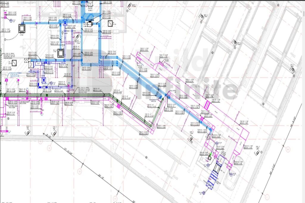
HVAC drawings show all ductwork, air conditioning units, ventilation fans, and the direction of airflow. It is used to distribute air properly in each room, ensuring that spaces stay cool or warm as needed. It also affects energy efficiency and occupant comfort.
→ Mechanical Equipment Layout
Displays the exact locations of chillers, cooling towers, pumps, and boilers. These layouts help engineers and technicians identify where to install or access equipment for servicing.
→ Ducting Layout
Details the shape, size, and route of ducts. Correct duct dimensions and placement are essential to prevent airflow resistance, maintain indoor air quality, and optimise energy consumption.
→ Piping Layout
This drawing shows chilled water pipes, condenser water lines, and refrigerant piping. It helps avoid interference with other systems and confirms appropriate pipe sizing and routing.
→ Exhaust and Fresh Air Layout
Exhaust systems remove contaminated air, while fresh air systems bring clean air into the building. This layout supports health and compliance with ventilation standards.
2. Electrical Drawings
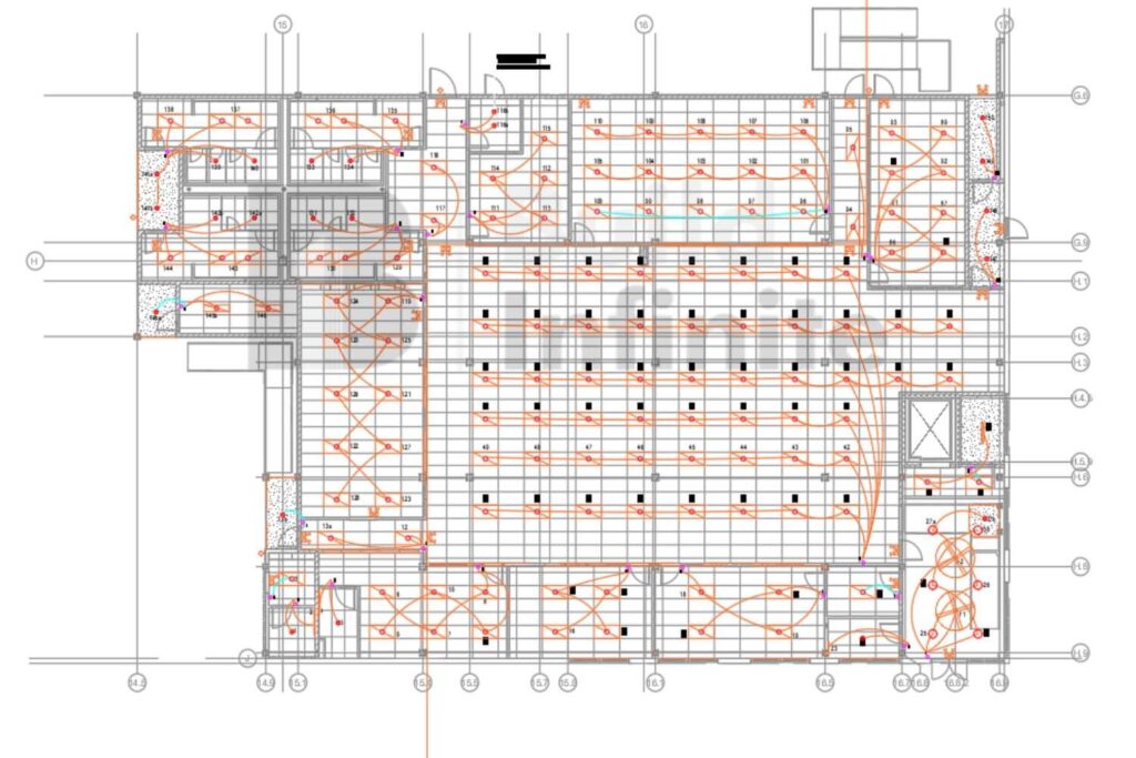
Electrical drawings detail how power is distributed throughout the building. They ensure safety, efficiency, and support for lighting, equipment, and appliances.
→ Electrical Power Layout
Illustrates power sources like transformers, switchgear, and distribution boards. It shows how electricity flows from the main supply to each device in the building.
→ Lighting Layout
Includes various lighting systems such as ambient, task, decorative, and emergency lighting. Proper lighting design improves visibility, mood, and safety in every space.
→ Single Line Diagram (SLD)
A simplified schematic showing how power is distributed using a single line representation. It includes symbols for breakers, fuses, and meters. Single Line Diagram is essential for troubleshooting and planning future electrical expansions.
→ Earthing and Lightning Protection Layout
Indicates how electrical systems are grounded to prevent electric shocks. Also shows how the building is protected from lightning strikes using rods and conductors.
→ Fire Alarm Layout
Details the locations of smoke detectors, fire alarm panels, and emergency communication systems. This is key for compliance and occupant safety in case of a fire.
3. Plumbing Drawings
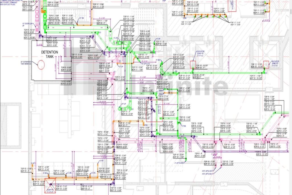
Plumbing drawings ensure the safe delivery of clean water and the removal of wastewater. They also cover gas systems and sanitary fixtures.
→ Water Supply Layout
Shows how clean, potable water is routed from the source to every fixture in the building. Includes pipe sizes, pump locations, and storage tanks.
→ Drainage Layout
Covers the movement of wastewater and stormwater out of the building. Includes drain pipes, inspection chambers, slope gradients, and vents.
→ Plumbing Riser Diagram
Shows vertical piping from one floor to another. It helps plumbers understand how to install and connect systems between multiple levels.
→ Gas Piping Layout
Details the safe distribution of gas for kitchens, heating, or industrial processes. Includes shut-off valves, leak detection, and safety features.
→ Sanitary Fixture Layout
Indicates the location of toilets, sinks, urinals, and bathtubs. Also shows connections to water and drainage systems, and required clearances.
4. Fire Fighting and Sprinkler Drawings
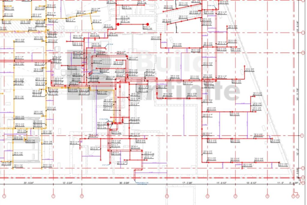
Fire Sprinkler Drawings show all the systems that detect and fight fires. They are vital for both prevention and emergency response.
→ Fire Sprinkler Layout
Details the network of sprinklers installed throughout the building. Includes pipe routing, sprinkler head locations, and water pressure requirements.
→ Fire Hydrant and Hose Reel Layout
Includes indoor and outdoor fire hydrants, hose reels, extinguishers, and emergency signage. Helps firefighters and building occupants quickly control fire outbreaks.
→ Smoke Extraction System
Shows fans, ducts, and control systems used to clear smoke during a fire. This is essential for safe evacuation and visibility.
Other Common MEP Drawings
Here are some additional drawings commonly used in large or bright buildings:
- BMS Layout (Building Management System): Integrates HVAC, lighting, fire alarms, and other systems into a centralised dashboard for automation and monitoring.
- Low Voltage Layout: Shows security systems, CCTV, access control, and intercom systems to ensure building safety and surveillance.
- Data and Communication Layout: Details cabling for internet, phones, and IT infrastructure. Crucial for modern offices and commercial spaces.
These enhance the intelligence and efficiency of buildings, especially in innovative city developments.
Why Use MEP Drawings PDF?
The choice of file format for these drawings is just as important as the drawings themselves. Using a MEP drawings PDF offers numerous advantages:
- Universal Compatibility: PDFs can be opened and viewed on virtually any device, from a desktop computer to a smartphone, without the need for specialized software. This allows everyone on the project team, from the project manager to the on-site contractor, to access the plans easily.
- Data Integrity: The PDF format ensures that the original formatting, fonts, and layout of the CAD (Computer-Aided Design) drawings are preserved. This prevents any inconsistencies or misinterpretations that could occur when sharing files between different software programs.
- Security and Control: PDFs can be password-protected to restrict access and editing. This is particularly useful for protecting sensitive design information and ensuring that only authorized personnel can make changes.
- Easy Sharing and Archiving: The compressed nature of PDFs makes them smaller in file size, which speeds up email transfers and cloud storage. They are also a stable format for long-term archiving, providing a reliable record of a building’s as-built condition for future maintenance or renovations.
By using the MEP shop drawings PDF, construction professionals can streamline their workflow, reduce errors, and ensure their projects are completed safely and efficiently.
Who Prepares the MEP Drawings List
Several professionals work together to create the MEP Drawings List. Each has a unique role:
- MEP Engineers: Design the systems, run simulations, and calculate requirements.
- Drafters/CAD Technicians: Turn designs into readable drawings using software.
- Architects and Structural Engineers: Coordinate spaces and ensure compatibility with walls, ceilings, and floors.
- Project Managers: Track progress and ensure that designs are aligned with the project timeline and budget.
They often use tools like AutoCAD, Revit, Navisworks, and BIM 360 to collaborate and create accurate, clash-free drawings.
Tips to Understand MEP Drawings Faster
Even if you’re new to construction or engineering, you can start understanding MEP drawings by following these tips:
Tip-1: Learn the symbols
MEP drawings use standard symbols for ducts, pipes, switches, and outlets. Study the drawing legend to recognise these.
Tip-2: Know the colour codes
Each system often has a colour. For example, blue is usually for water, red for fire systems, and green for drainage.
Tip-3: Follow the scale
Drawings are scaled down. For instance, 1:100 means 1 unit on paper equals 100 units on site. Always check the scale.
Tip-4: Ask questions
If something looks confusing, ask the engineer or your supervisor. Understanding now can save time and prevent mistakes later.
Codes and Standards MEP Engineers Follow
MEP Engineers work with many other disciplines, and their design will always reflect other trade inputs.
MEP Engineers will also rely on other design documents and will integrate various engineering design codes such as: MEP codes, local building codes, National Fire Protection Association codes, American Society of Heating, Refrigerating and Air-Conditioning Engineers, Institute of Electrical and Electronics Engineers codes, National Electric Code, and others as applicable.
Drainage and Venting codes will be applicable to Plumbing Systems, and design layouts for Fire Protection Systems will be graded based on the density and distribution of Sprinklers.
Compliance with these standards will be maximum, as there will be a significant liability regarding safety and costs related to the redesign process should the relevant codes and standards not be observed during the design phase.
MEP engineering firms have the resources to keep abreast of recent changes to codes and standards on a regional and international level to ensure that design drawings will be approved on first submission. Reviewing the MEP drafting partner should always include verification that they are well informed on the codes relevant to the jurisdiction of the project and the type of building.
Common Mistakes in MEP Drawings
Avoid these frequent issues:
- Overlapping ducts and pipes that don’t fit in real space
- Poor coordination between floors leads to broken connections
- Inaccurate pipe sizes that affect performance
- Missing annotations and notes that confuse workers
- Unclear riser diagrams that don’t explain vertical piping correctly
Always do a detailed review and coordination check before issuing drawings for construction.
How the MEP Drawings List Impacts Construction
Think of the MEP Drawings List as the brain behind your building. Every wire, pipe, and duct follows these instructions.
Benefits during construction
- Clear installation steps for workers
- Minimal on-site rework or delays
- Easy code compliance and approvals
- Higher quality and artistry
Benefits after construction
- Easier maintenance and repair work
- Simplified building upgrades in the future
- Reduced safety risks and utility failures
MEP Drawings in BIM Projects
Today, many teams use Building Information Modelling (BIM) to improve MEP design and coordination. BIM creates a 3D digital model that integrates all building systems.
With BIM, you can:
- Visualise potential clashes in 3D before construction begins
- Run simulations for energy and performance
- Collaborate live across teams and disciplines
MEP Coordination and Pre-Fabrication Drawings
The more complicated our buildings get, the more important MEP coordination drawings become to eliminate clashes before the building process begins. MEP coordination drawings are typically 3D drawings made using BIM software, like Navisworks or Revit. MEP models can be brought into a single coordinated view. Engineers can identify clashes with ductwork, piping, and cable trays before anything is installed on site.
MEP prefabrication modeling builds off MEP coordination drawings, where coordinated drawings are transformed into prefabrication models and drawings for fabrication. Rather than relying on manual assembly of ductwork or piping on site, a module that is prefabricated is constructed off site, with measurements that are precise to the coordinated model, and is delivered to site for installation.
The combination of 3D coordinated shop drawings and prefabrication means that this process is remarkably efficient and preferred for massive commercial and healthcare projects. This system also decreases errors and minimizes the amount of manual labor that is required to be present on site.
Which Drawings Show Air Conditioning?
Air conditioning systems in buildings are represented in specialized construction drawings known as MEP (Mechanical, Electrical, and Plumbing) drawings.
Within MEP, the mechanical drawings specifically show the details of heating, ventilation, and air conditioning (HVAC) layouts. These drawings illustrate the placement of air handling units, ductwork, diffusers, vents, return air grilles, and refrigerant piping, providing contractors and engineers with precise guidance during installation.
In architectural projects, HVAC drawings are often overlaid on floor plans or reflected ceiling plans to show how the system integrates with the structure. They highlight duct routes, air conditioning equipment, and airflow directions, ensuring proper distribution of cooled air throughout the building.
For Large-scale projects, schematic diagrams or one line diagrams may also be included to represent system connections and control logic in a simplified format.
In residential projects, mechanical floor plans typically show the locations of split AC units, outdoor condensing units, and refrigerant lines. In commercial and industrial buildings, these drawings are more detailed, showing chilled water systems, packaged units, VRF/VRV systems, and ventilation strategies.
Air conditioning layouts are critical not only for installation but also for energy efficiency, maintenance, and compliance with building codes. They allow coordination between architects, structural engineers, and MEP consultants, avoiding clashes with beams, electrical conduits, or plumbing lines.
In summary, air conditioning is shown on mechanical or HVAC drawings within the MEP set of construction documents. These plans provide the blueprint for accurate installation, performance optimization, and long-term system reliability.
What files are needed to prepare MEP shop drawings for a Villa project from Architect drawings?
Engineers need every document to make MEP shop drawings for villa projects. They need to get every system right and want every coordinate detail. The most important document is the architectural floor plan. This contains information on the arrangement of space, where walls will be, where openings will be placed, and the dimensions and tolerances of the elements.
In addition to this, elevations and sections give information on available space for elements and structures for vertical and horizontal clearances.
With these documents, engineers also require structural drawings, as these give the dimensions and locations of columns, beams, and foundations to aid MEP coordination. Ceiling design also needs to be shown to know where ceiling-mounted services will be placed. For MEP services, design drawings of HVAC, plumbing, electrical, and fire protection systems should also be available.
Most designers send these through DWG, DXF, RVT, or PDF. CAD and BIM files help designers and engineers work faster and produce more accurate and coordinated drawings. MEP shop drawings are made more detailed and accurate with project specifications, equipment and material schedules, and data sheets.
Having all of these, designers can produce drawings that ease and simplify installation and improve and aid the construction and design of residential projects.
MEP Drawings Across Building Types
Every type of building has an MEP design that is unique to the building type. For commercial buildings, MEP design will account for easily adjustable zoning for HVAC, flexible electrical distribution, and flexible layouts for commercial Tenancy Fit-Outs.
MEP design for hospital buildings is more complex and needs to account for piping for medical gas systems, Isolated Power Systems (IPS), negative pressure rooms, and Infection Control (IC) ventilation standards.
MEP design for office buildings focuses on the design and integration of energy-efficient lighting, flexible structured cabling and IT systems, and HVAC systems that are comfortable and comply with building and health codes for high-density occupancy.
In educational buildings, MEP design has its own unique challenges. MEP consultants for the design of educational buildings need to integrate walls of classrooms that minimize sound, classroom ventilation, and specialized plumbing and gas requirements for laboratories, all while working with a limited budget.
Understanding the challenges and requirements for flexible MEP design is crucial; MEP design does not work if you apply a single solution across the board. Working with an MEP consulting firm with a lot of experience will ensure that your design meets your ideas and work needs.
Conclusion
Whether you are a student, a site engineer, or a builder, knowing the MEP Drawings List helps you stay organized, reduce mistakes, and build better structures. These drawings are more than paper – they are the language that engineers and construction teams use to bring buildings to life.
Make sure you have the correct drawings, the right team, and the right tools. That’s the formula for success in construction.